920C Control Panel project
Reviving an Elliott 920C control panel
As a vounteer at the UK National Museum of Computing (TNMOC), I've started a project to breath life into this 1960s Elliott 920C control panel.

This
is just the control panel module for a 920C computer, which sadly we don't have as
an exhibit. So at present it's a static exhibit. The original idea was to simply animate the control panel by
lighting the lamps by flicking a switch. This has significantly expanded into actually
building a Raspberry Pi Elliot 900 Emulator*, and controlling it from the 920 control panel. A perfect example of Scope Creep at its finest !
* There is an active Elliott 900 Emulator community, I've selected Andrew J Herbert's 900 Emulator in C, as Andrew is handily close by for many questions - he is the chair of the TNMOC Trustees !).
Initial feasability tests
The initial 2 tasks was to get a Pi C software framework in place to read switches and light lamps, and secondly see what's inside the Control Box.

As there are a
multitude of switches & lamps in the 920C box, many more than there are Pi GPIO pins to drive them; I decided on the I2C card to get the additional I/O ports. You can see my test cards for switches and LEDs, which are all driven by the I2C card.

From
previous Elliott restorations my
co-conspirator Peter Williamson knew that the switches would have spare
connectors that we could use, without doing any damage. These have been tested with a multimeter.

The front panel above photo above shows our
first test - to use the lamp driver to light a lamp, triggered by a
signal from the Pi (in this case a GPIO pin). We also piggy backed the Pi +/- 5V supply for the 920 circuitry. The actual voltage inside the 920 is 6V, but all seemed to work.
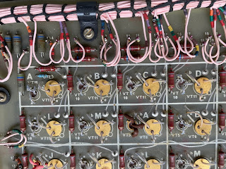
PeterW has found a convenient spot to connect a trigger wire.
I have compiled the 900 Emulator C code on my Pi400 had a tinker, and I think I now know enough to be dangerous ;o)
Sadly the external connectors on the rear of the 920C box seem to be very old MilSpec jobs, and will not be easy to source (or solder for that matter - the larger one has > 50 connectors !)

So far, so good, all our feasability tests are completed.
18/122/2021 update:
Design
The main components are centred around a Raspberry Pi 4, with HAT expanders - 2 x AB Electronics I2C, and generic GPIO header. There is a RS 5v 10A psu, some project board and port repeaters through the case for HDMI, keyboard, mouse and USB-C connector. Wiring to the 920C will be via DB25 connectors.


(11/01/22 update)
Slow progress due to the amount of soldering, and I'm not an electronics hobbyist.
I have managed to solder the 40-pin GPIO headers, and 20 pin connectors to the I2C boards, and to build the HAT stack.

Today I'm adding the 20+ resistors to the project board in the photo. Next job is to install all the bits into the radio case and test.

I've the components for a "production build"
- a Pi 4b (4Gb ram - doesn't need that much, but was the smallest in stock @ PiHut)
- Pi HAT expanders 2 x I2C, and a GPIO connector), a tatty old radio case to house the all bits (rescued from the TNMOC skip next to Hut 24)
- an old screen from the TNMOC office to use to run the PPT & TTY input/output emulation software.
- A beefier RS 10Amp PSU for the 5amps needed to drive all the 920 circuits (plus up to 3amps for the Pi) ,
- DB25 connectors (ubiquitous and realtively easy to solder),
- Pi USB/HDMI etc port replicators to fit on the case.
- Bit of perspex for the radio case back panel and to host the necessary holes for DB25 connectors
Next steps
- Assemble all the bits, and solder, solder, solder !
- Wrap the 900 emulator software with a GUI, that also interreacts with the Pi 920 driver I've written.
- Add some non-invasive connectors to the 920 swicthes & lamp-driver circuits.
- Make-up the DB25 connector cables.
Comments
Post a Comment